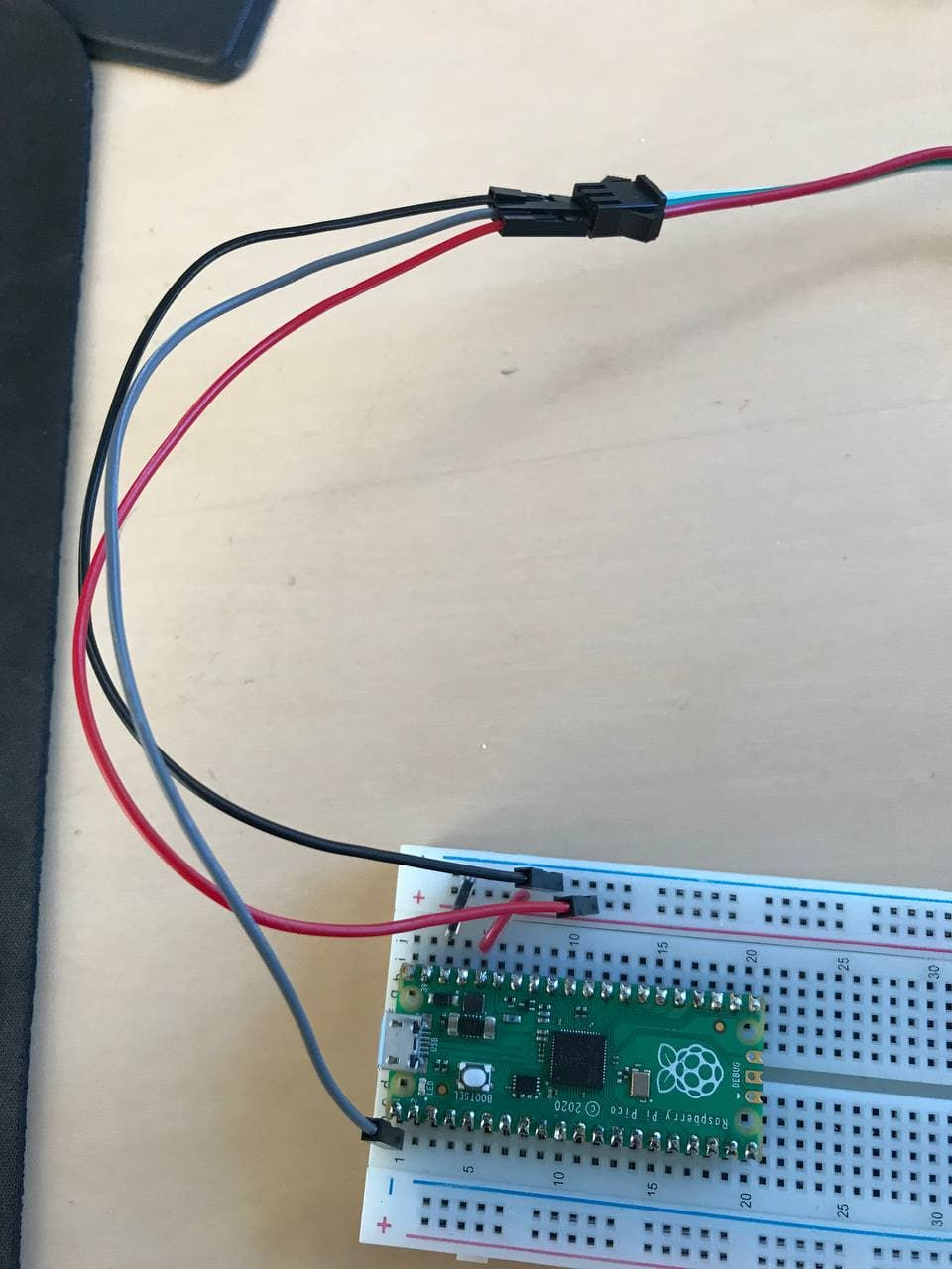
It's Christmas time, you forgot to get a big tree for your house/apartment/office. But don't worry, you found a $5 Family Dollar tree.

One step above Charlie Brown's Christmas Tree... and it's missing that je ne sais quoi. But it's ok, you have a spare Raspberry Pi Pico and a string of 10 WS2812B NeoPixel LEDs.


NeoPixels are individually addressable LEDs, each with their own tiny controller. When you send data to them, the first on the line reads in 24 bits of data (GRB, because why would it be RGB?) and passes the rest of it down the line. Animations are accomplished by sending a reset signal and then a new stream of data.

The actual protocol for the serial data is a little interesting. So instead of just pulsing the DATA line with 0's and 1's for our bits, we have to implement the following protocol:

So to send a zero, we pulse high for a certain amount of time, then go low. And to send a one, we... do the same? The missing factor here is the timing:

Luckily, the high and low voltage times differ by a margin less than the tolerance, so we can consider them to be the same. So, a long signal is going to be 2/3rds of our "packet" and the short signal is 1/3rd. The best way of implementing this protocol is by using the programmable I/O on the Pico (PIO). Using PIO blocks, we can implement simple programs (or in this case, communication protocols) and have our main program pipe data to or from the PIO block. Our PIO block program would, in this case, take a bit from our program, and put the appropriate signal on the data line. Pseudocode:
1. Read a bit.
2. Write a 1 (high pulse) to the out pin.
3. If the bit was 1, stay high. If it was 0, go low.
4. Go low, if we haven't already.
5. Go to 1.
When we implement this in PIO assembly, there a few important considerations: We only have 2 scratch registers, an input and output register, very limited commands, but we do have a unique ability to set our output pin's value at the same time as we perform other commands, an ability known as side_set. The format of a PIO assembly instruction is as follows:
<instruction> (side <side_set_value>) ([<delay_value>])So was can do stuff with registers, jump, compare, etc., while setting the pin value and optionally delaying a certain number of cycles before proceeding to the next instruction. Putting this all together looks like this:

PIO assembly
.program ws2812
.side_set 1

.define public T1 1
.define public T2 4
.define public T3 2

.wrap_target
loop:
        out x, 1 side 0 [T3] ; side-set to zero while waiting for bit
        jmp !x do_zero side 1 [T1] ; side-set to one
do_one:
        jmp loop side 1 [T2] ; if bit was 1, keep driving high
do_zero:
        nop side 0 [T2] ; drive low
.wrap

% c-sdk {
#include "hardware/clocks.h"

static inline void ws2812_program_init(PIO pio, uint sm, uint offset, uint pin, float freq, bool rgbw) {
    pio_gpio_init(pio, pin);
    pio_sm_set_consecutive_pindirs(pio, sm, pin, 1, true);

    pio_sm_config c = ws2812_program_get_default_config(offset);
    sm_config_set_sideset_pins(&c, pin);
    sm_config_set_out_shift(&c, false, true, rgbw ? 32 : 24);
    sm_config_set_fifo_join(&c, PIO_FIFO_JOIN_TX);

    int cycles_per_bit = ws2812_T1 + ws2812_T2 + ws2812_T3;
    float div = clock_get_hz(clk_sys) / (freq * cycles_per_bit);
    sm_config_set_clkdiv(&c, div);

    pio_sm_init(pio, sm, offset, &c);
    pio_sm_set_enabled(pio, sm, true);
}
%}
I know there's a similar version of this available in the pico-examples repository, but I did want to try to do this myself for a better understanding of the PIO language. The `side_set` directive means that we are reserving 1 bit of the delay value parameter for sending information to our pins. The exact pins to use are selected in the program_init function at the bottom, which is called from our main program using names autogenerated by the build system (which is too far in depth for even me to worry about). One difference between here and the pico-examples version is that they used an expression for the delay, so their T-values were one higher than they needed to be. I'm pretty sure that might have been optimized later, but in any case, it wasn't necessary.

Once this is set up, the C is pretty straightforward:
#include "hardware/clocks.h"
#include "hardware/pio.h"
#include "pico/stdlib.h"
#include "ws2812.pio.h"
#include <stdio.h>

int main() {
  PIO pio = pio0;
  int sm_id = 0;
  uint offset = pio_add_program(pio, &ws2812_program);

  ws2812_program_init(pio, sm_id, offset, 1, 800000, false);
  int ledoffset = 0;
  while (true) {
    for (int i = 0; i < 10; i++) {
      if (i % 2 == ledoffset) {
        pio_sm_put_blocking(pio0, sm_id, 0xff000000);
      } else {
        pio_sm_put_blocking(pio0, sm_id, 0x00ff0000);
      }
    }

    ledoffset++;
    if (ledoffset == 2)
      ledoffset = 0;
    sleep_ms(500);
  }
}
Or you could just use the Adafruit WS2812B library and do this in MicroPython.
コメント